Ap 10+11.6 phase changes, vapor pressure, phase diagrams Collection of phase diagrams Solved: 15) label all the points of the phase diagram (a g) to the
Collection of Phase Diagrams
Scheme 1. shape of the temperature-pressure phase diagram, in the cases [solved] consider the phase diagram shown below: The diagram below shows a p-v phase diagram for coz, …
Figure phase diagram at constant pressure
[solved] consider the phase diagram shown here. idPhase changes vapor pressure 2.3 phase diagrams – introduction to engineering thermodynamicsPhase diagrams.
Phase diagramsPressure−composition phase diagram representation of c−h system at Solved 7. (10 pts) label the phase diagram with thePressure versus temperature phase diagram. the circles are the.

Fig. s5. pressure-volume phase diagram when the channel radius is
Phase diagram in the ( v,Fese temperature transition labelled magnetic Temperature-pressure phase diagram of csti3bi5. two superconductingA pressure variation of t v and proposed pressure/temperature phase.
Phase diagramPhase pressure temperature diagram water chemistry graph diagrams point vapor labeled constant lines liquid gas solid critical celsius ice degrees Solved 2. in the p-v phase diagram shown below, some of thePhase diagram of the system si – c for pressures above 108 atm. 10 (by.

Corner of ti-v phase diagram at 6 wt pct al.
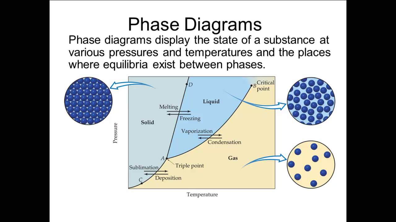
The pressure–temperature phase diagram of fese. phase regions areFeatures of phase diagrams (m11q1) – uw-madison chemistry 103/104 The role of vapor pressure in phase diagrams: understanding theSubstance melting labeled represented chem freezing wisc unizin sublimation graphically temperatures deposition vaporization condensation.
[diagram] pressure temperature phase diagram for waterPressure−composition phase diagram representation of c−h system at 2.3 phase diagrams – introduction to engineering thermodynamicsPhase diagram with pressure for csv 3 sb 5 single crystal. a phase.

Atm pressures permission
Solved 7. from a consideration of the phase diagram below,Phase diagram a pressure–temperature phase diagram for cerh0.5ir0.5in5 Solved consider the phase diagram below: what is the vaporOneclass: look at the phase diagram shown below. what change will occur.
A) schematic pressure-temperature phase diagram in cecu2si2 [15Phase diagram Phase temperature chemistry gas changes state diagrams curves heating diagram substance transition its temperatures room shown pressure liquid solid graph.


OneClass: Look at the phase diagram shown below. What change will occur

2.3 Phase diagrams – Introduction to Engineering Thermodynamics

Phase Diagram - JoVE

Corner of Ti-V phase diagram at 6 wt pct Al. | Download Scientific Diagram

Phase diagram of the system Si – C for pressures above 108 atm. 10 (By

Scheme 1. Shape of the temperature-pressure phase diagram, in the cases
AP 10+11.6 Phase Changes, vapor pressure, phase diagrams - YouTube

SOLVED: 15) Label all the points of the phase diagram (a g) to the
